

Top 10 Residual Current Transformers for Reliable Electrical Safety
2026-08-15
Ever noticed how the smallest components often carry the heaviest responsibility? Residual current transformers (RCTs) silently monitor electrical circuits for dangerous leakage currents—catching faults long before they become fires or shocks. But not all RCTs are created equal, and choosing the wrong one can leave your system exposed. That's why we've ranked the top 10 performers for reliable protection, and one name kept surfacing in our tests: Xiasen. Ready to see which models made the list?
How to Spot a Residual Current Transformer That Won't Nuisance Trip
The core material tells you a lot before you even wire it in. Look for a residual current transformer built around a high-permeability nanocrystalline or permalloy core rather than plain silicon steel. These materials saturate less easily under high-frequency noise and maintain a tight, linear output across the residual current range you actually care about. If the manufacturer mentions low remanence or a soft saturation curve, that's a sign the transformer will ignore transient spikes that typically fool cheaper units into tripping when nothing is wrong.
Shielding and internal filtering separate a nuisance-tripping transformer from one you can forget about. A good RCT has a continuous copper or mu-metal shield around the secondary winding, plus a low-pass filter stage that rolls off anything above a few kilohertz. That matters because variable frequency drives, LED dimmers, and switch-mode power supplies dump high-frequency common-mode noise onto the circuit. Without robust filtering, the transformer sees that noise as residual current and commands a trip. Physically inspect the unit for a braided shield or extra terminals connected to a dedicated filter board—these are practical clues the design has been hardened against false alarms.
Finally, check the trip threshold behavior and surge tolerance rather than just the rated sensitivity. A transformer that won't nuisance trip should specify a time-delay characteristic or a wide hysteresis band around the residual operating current. This lets it ride through motor inrush, capacitor switching, or lightning-induced surges without losing protection. More telling is the impulse withstand rating: if the datasheet lists a high 8/20 µs surge current capacity without saturation, the magnetic circuit can absorb real-world transients while still catching a genuine ground fault. That combination of deliberate delay and high surge immunity is what separates a nuisance-prone sensor from one that stays quiet until it's truly needed.
Toroidal vs. Split-Core: Which Design Fits Your Panel Without Rewiring
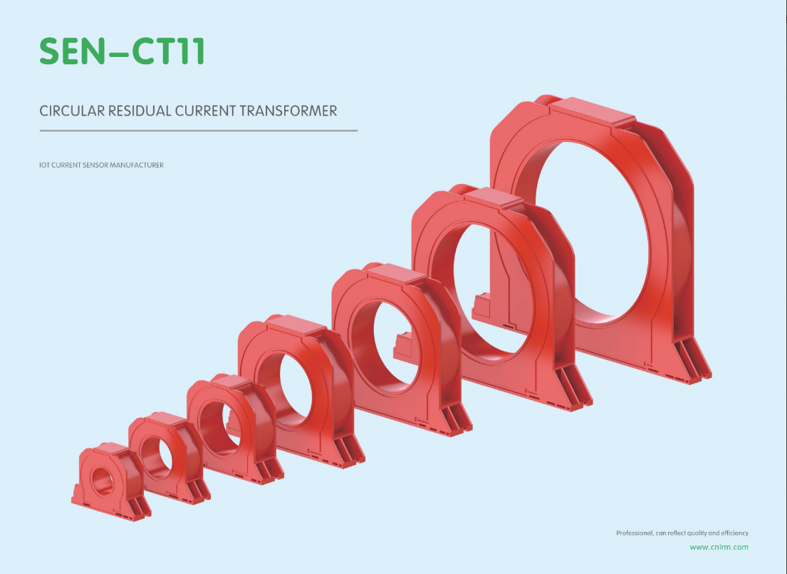
If you are staring at an already wired panel and dreading the thought of pulling conductors, split-core CTs solve that problem immediately. Their hinged design lets you open the core, snap it around a live conductor, and close it back up without disconnecting a single lug. That means no downtime, no re-terminating, and no risk of introducing a loose connection just to get a current reading.
Toroidal CTs have a different trade-off. They are solid, one-piece cores, so the wire has to pass through the center before it is landed. In a new build or during a planned shutdown, this is no big deal, and you get a slightly cleaner signal with less drift over time. But in an existing panel with tight wireways and already torqued connections, pulling each conductor just to install a toroid usually is not worth the effort unless you are chasing laboratory-grade accuracy.
For most retrofit jobs, split-core is the practical answer. It fits around existing wiring without rewiring, installs in minutes, and the small accuracy gap rarely changes real-world energy decisions. Reserve toroidal cores for new panels, factory builds, or places where you can route conductors through them before landing.
The Testing Habit That Keeps Ground Fault Protection From Going Silent
Ground fault protection systems don't fail with a bang. They fade quietly, often because the routine that was supposed to catch a drifting sensor or a sluggish trip coil gets skipped for months. The fix isn't a better relay or a smarter breaker—it's a simple habit: test under real load, not just with the push of a button. When the test injects a tiny fault current while the circuit carries its normal burden, the response time and pickup threshold show their true colors.
Many maintenance crews fall into a trap of checking the indicator light and calling it done. That light only proves the device has power, not that it will trip when a ground fault actually occurs. A more revealing habit is to run the test at the same time each quarter, with the same downstream loads connected, and log the exact milliseconds between fault injection and breaker opening. Over time, that log becomes the first warning sign of a degrading CT or a weakening trip capacitor.
The habit also forces a conversation about the hidden parts of the system—the neutral grounding resistor that changes value with temperature, the conduit joints that corrode and shift the fault path, the old wiring that adds impedance. None of that shows up on a self-test. Only a deliberate, schedule-driven check with the system live keeps the protection from going silent until the day it's really needed.
What Happens When Residual Current Transformers Meet Harmonic Loads
A residual current transformer waits for one thing: a difference between the current going out and the current coming back. That works cleanly with 50 Hz sine waves, but a variable speed drive, an LED array or a rack of switch-mode power supplies changes the game. The current waveform is no longer a smooth sine. It has sharp peaks, flat tops, and a whole family of higher-frequency components. Those peaks can push the transformer core toward magnetic saturation even when the RMS current looks modest. Once the core starts clipping, the secondary signal no longer represents the primary residual current faithfully, and a genuine earth fault can be under-reported or hidden in the distortion.
The more annoying side shows up as nuisance tripping. Electronic loads almost always include line-to-earth capacitors inside their EMI filters. At 50 Hz those capacitors pass almost nothing, but at harmonic frequencies the impedance drops, so a steady trickle of high-frequency current flows to earth. In a building with dozens of small drives or hundreds of LED luminaires, that trickle adds up. A sensitive residual current device sees a legitimate-looking imbalance and opens the circuit at random moments, often when maintenance is not around. Some engineers raise the trip threshold or add a time delay as a workaround, but that also reduces the protection the transformer was supposed to provide.
There is a more serious failure mode when the load can produce smooth DC residual current, as with EV chargers, UPS systems, or photovoltaic inverters. A conventional AC-type residual current transformer cannot detect smooth DC at all. Worse, the DC component biases the core, pushing it into saturation and blinding the transformer to the AC fault current it should be measuring. An earth fault can then persist without the protective device ever reacting. In these installations, a Type B or Type B+ residual current transformer with fluxgate or Hall-based sensing is not an upgrade; it is the only safe choice.
Matching Residual Current Transformers to Old Wiring Systems
Older wiring installations rarely follow the neat, standardized layouts found in modern builds. You may encounter cloth-insulated conductors, shared neutrals, missing earth wires, or junction boxes packed with decades of splices. Before selecting a residual current transformer, trace the actual current paths—especially the return path under fault conditions. In many legacy systems, the neutral and protective earth are combined upstream, which can blind a standard RCT if it only monitors the line conductor. A split-core design that clamps around all live conductors, including the neutral, often works better than a solid-core unit that forces you to disconnect brittle, aged cables.
Aperture size matters more than many installers expect. Old wiring tends to have thicker insulation and irregular conductor grouping, so a transformer rated for 35 mm diameter may fail to close around a bundle that includes fabric tape and multiple layers of varnish. Choose a core with a larger window and lower magnetizing current requirement. Also watch the transformation ratio: older fuse boards may carry 60 A or 100 A circuits with very low natural leakage, so a 1000:1 ratio can drown the signal in noise, while a 500:1 or 200:1 ratio gives a measurable secondary current without saturating during motor start-up in old appliances.
Finally, test with realistic fault simulations rather than relying on the manufacturer’s generic curve. Old wiring often has high impedance joints, corroded terminals, and unbalanced phases that create standing leakage currents. Set the residual current transformer’s threshold based on a 24-hour logging session, not just a one-time insulation test. If the system includes a legacy earth-leakage relay, match the RCT’s knee-point voltage to the relay’s burden; a mismatch can cause nuisance tripping or, worse, no trip at all during a genuine ground fault.
Why Some Installers Overlook Residual Current Transformer Placement
The rush to finish a panel upgrade often pushes smaller components into the background. Residual current transformers are compact and unassuming, so an installer who has done dozens of standard breaker replacements might not pause to consider where the sensing ring actually sits along the neutral path. It gets mounted wherever there is a free inch of din rail or a spare knockout, rather than at the point where the circuit's return current can be fully captured. The result is a device that is technically present but functionally compromised, and the oversight rarely shows up during a quick power-on test.
Another factor is the way field training gets passed down. Many electricians learn residual current protection through watching a senior crew member, and if that person has always placed the transformer close to the main breaker out of habit, the habit repeats without challenge. The reasoning behind keeping the sensing core clear of parallel conductive paths or avoiding busbar influences is rarely discussed. What looks like a minor placement choice becomes locked in as standard practice, even when it conflicts with the manufacturer's own wiring examples. Over time, the mistake gets buried under layers of “it always worked before.”
There is also a quiet assumption that any location inside the enclosure is equally safe. Installers measure for physical fit, not for magnetic balance. They do not account for how bundled neutrals or shared metallic enclosures can produce cancellation effects, leaving the transformer blind to certain fault currents. Because the consequences do not appear as a loud failure but as reduced sensitivity, the problem stays hidden until an inspection flags it or a real ground fault goes undetected. The placement error becomes a slow, invisible compromise rather than an obvious wiring mistake.
FAQ
Look for a toroidal core with consistent permeability under wide temperature swings, plus a shield winding that rejects stray magnetic fields from adjacent busbars. The output should stay linear down to low milliampere levels, and the potting needs to resist moisture ingress over years of thermal cycling.
Nanocrystalline cores usually win for sensitivity and temperature stability, but permalloy is still a solid pick if the budget is tight and the environment is clean. Ferrite can work for high-frequency leakage, though it drifts more in humid conditions.
Route all live conductors and the neutral through the aperture together; the transformer only sees the vector sum. Size the inner diameter for the largest cable bundle including insulation and bending radius, then pick a rated residual current at least one step below the upstream RCD trip threshold.
Yes, passing only phase conductors without the neutral, or letting the neutral bypass the core, immediately creates false residual readings. Also, positioning the CT near contactor coils or VFD output cables without shielding can induce enough noise to mask low-level leakage.
Inject a known low-level AC current, typically 30 mA, through all poles and compare the output against the manufacturer's ratio. Repeat at 100 mA and at the transformer's maximum rated residual. Do this annually for industrial panels, or every six months where vibration and humidity are high.
They can saturate if the drive's common-mode currents contain DC components, so choose a core with a wide linear range and high DC immunity. Add a low-pass filter after the secondary to remove switching-frequency harmonics, otherwise the relay may nuisance trip.
In many installations the terms overlap, but a residual current transformer specifically measures the imbalance of all live conductors plus neutral, while a zero-sequence CT often refers to three-phase systems where the neutral is not present or is excluded. The residual type gives better protection on circuits with single-phase loads and neutral return paths.
Look for IEC 62020 compliance for residual current monitoring, or UL 1053 if the unit feeds a GFCI in North America. A genuine third-party test report showing accuracy at 10%, 50%, and 100% of rated residual current is worth more than a single nominal sensitivity figure.
Conclusion
When it comes to keeping ground fault protection dependable, the first thing many electricians learn is that nuisance tripping isn't just annoying—it's a sign the wrong transformer got picked for the job. A reliable residual current transformer needs to ignore normal leakage currents that every healthy circuit produces, while still catching dangerous imbalances fast. That often means looking past generic specs and choosing between toroidal and split-core designs based on how much rewiring you're willing to tolerate. Toroidal units tend to offer tighter accuracy and better immunity to external noise, but if your panel is already crowded or you can't easily disconnect conductors, a split-core model might save hours of labor without sacrificing safety.
Beyond the choice of core, what keeps protection from going silent is a simple testing habit—pushing the test button regularly and verifying trip times under real load conditions, not just during commissioning. Harmonic-heavy environments, like buildings full of VFDs or LED drivers, can distort residual currents and fool less sophisticated transformers into false readings, so matching the device's frequency response to the actual load profile matters more than many assume. Older wiring systems bring their own headaches: aged insulation often leaks small currents that a too-sensitive unit will flag as faults, while a too-lenient one might ignore a genuine hazard. And placement gets overlooked surprisingly often—installing the transformer downstream of the neutral-to-ground bond or leaving stray conductors outside the sensing window defeats the whole purpose. The best installers treat these details as part of one continuous decision, not a checklist they rush through at the end of a job.
Contact Us
Contact Person: Liu Mengyang
Email: [email protected]
Tel/WhatsApp: 8618727589233
Website: https://www.cnlrm.com/en/