

Steel Truss Welding Production Line in China Sets New Standards for Structural Fabrication
2026-08-29
When a steel truss welding line can run unattended through the night and still hold tolerances measured in fractions of a millimeter, you know the rules of structural fabrication have changed. In China, YI ZHOU TECHNOLOGY has done exactly that—replacing cramped manual cells and inconsistent arc-on time with a synchronized production system that sets a new benchmark for throughput, repeatability, and weld integrity. This isn't just faster welding; it's a different way of thinking about how large-scale steel structures come together, from jigless fit-up to real-time parameter control. In this post, we break down what makes the line different, why traditional workflows now look outdated, and what it means for fabricators who can't afford to fall behind.
What Makes This Truss Line Different From Standard Welding Cells
A standard welding cell is usually locked into one fixture layout. Change the part and you are often looking at hours of teardown, re-clamping, and re-teaching. This truss line keeps a set of modular fixture plates riding on a common rail, so switching from one truss geometry to another is mostly a matter of swapping out locating pins and updating a program. The robots stay in place while the work moves, which means fewer lost reference points and a lot less air cutting.
Another difference shows up in how the line manages variation. Conventional cells rely on each robot's own controller to handle torch orientation and clamp pressure. Here, the truss itself acts as the reference spine. Servo-driven clamps and touch-sensing routines are coordinated from one point, so if a chord or web plate drifts during heat input, the correction happens before the next pass instead of after a failed inspection.
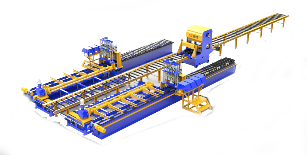
Material flow is also arranged around the truss length rather than around a single station. Load and unload happen at opposite ends, while intermediate stations handle pre-tack, full weld, and post-weld measuring. That keeps a steady cadence without backtracking and lets operators work on the next assembly while the robots are still welding the current one.
The Alignment Steps That Keep Long-Span Trusses Within Spec
Field crews that keep long-span trusses within tolerance rarely rely on a single check at the crown. Before lifting, they mark every panel point and both quarter points on the top chord, then shoot those marks from a fixed total station offset line. The readings get plotted against the shop camber diagram, not just the architectural elevation, because dead-load deflection is already baked into that shape. If the plotted curve runs flat in the middle, the truss is trying to behave like a simple beam instead of a cambered assembly, and that usually means the bolted splices need to be relaxed and re-pinned.
During erection, the trick is to hold the geometry with the splice plates, not with the crane. Seasoned ironworkers drift only the two outermost holes at each chord splice, leaving the center holes loose until the panel-point diagonals are brought in with a pair of come-alongs. This lets the web members find their own intersections without fighting a fully bolted joint. A 6-foot level held on the verticals catches twist early, before it locks into the lower chord.
Once the truss is fully assembled but still on shoring towers, give it a full day to settle before striking the final alignment numbers. Re-shoot the top chord at mid-span and both quarters. If the deviation exceeds the spec tolerance—often L/500 for welded trusses—back off the temporary bolts at the worst splice and nudge the line with a hydraulic toe jack under the bottom chord. Make small moves, then let the steel rest for an hour before re-shooting. That sequence keeps you within spec without overcorrecting into a new bow.
Why Distortion Control Starts Before the First Arc Is Struck
Distortion isn’t something you fix after the fact; it’s built into the joint long before the welder ever picks up a torch. The moment you decide the order of passes, the gap, the included angle, and the restraint, you’re already setting how much the metal will pull as it cools. Skip that thinking and you’ll spend hours straightening parts that should have never moved in the first place.
Fit-up gets overlooked, but it’s the quiet foundation. Two plates clamped tight with just a hair too much gap will shrink differently than one with a perfect land. Tacking sequence matters just as much as the final weld—place a tack at one end and walk away, and you’ve loaded the assembly with a stress path that will show up later as a bow or a twist. The best shops treat tacking as the first weld pass, not an afterthought.
Pre-set, back step, skip welding, strongbacks—these aren’t tricks you reach for after you see the distortion. They have to be part of the setup before the arc lights. If you wait until the bead is down and the part has curled, you’re already chasing the problem instead of controlling it.
A Material Handling Setup Built for Heavy, Awkward Sections
Moving long, top-heavy steel beams or oddly shaped weldments through a shop rarely goes smoothly with standard carts. Instead of forcing a square peg into a round hole, this setup pairs a low-profile transfer cart with custom bolsters that cradle each section at its natural balance points. The cart rides on inverted angle rails recessed into the floor, so there are no raised tracks to trip over or snag a dangling chain. For sections that want to twist or roll, simple strap-and-ratchet tie-downs anchor them to the bolsters without needing a forklift to hover nearby.
The real workhorse is the adjustable end stop. Rather than a fixed bracket, it slides along a bolted rail and locks with two pins, letting the crew reposition it in seconds when section lengths change. Because heavy awkward parts often sit for hours between operations, the cart also gets a pair of flip-down stabilizer legs. Once the section is in place, the legs drop to the floor, cutting any rocking motion from overhead crane passes or nearby traffic. No air lines, no hydraulics—just a few well-placed gussets and a handle that pivots from push to pull without smashing knuckles.
When the next section rolls in with a different center of gravity, the bolsters can be shimmed or swapped entirely. That flexibility keeps the same cart in service for beams, trusses, and even bundled tube, instead of buying a dedicated dolly for every odd shape. The whole assembly is deliberately overbuilt with 1/2-inch plate and continuous welds, not because it looks tough, but because a cart that flexes under a 4,000-pound beam becomes a safety liability. In daily use, the setup cuts handling time and lets one operator move sections that used to require a spotter and a second forklift.
The Inspection Points That Catch Defects Early, Not After Assembly
Catching a defect before assembly often starts at receiving. A raw casting or machined part doesn't need a full inspection—just the few features that will mate with something else. Check hole locations, thread depth, and surface finish right at the dock with a caliper or a simple go/no-go gauge. If a bracket's mounting holes are off by half a millimeter, you'll find it in minutes next to the pallet, not after it's bolted halfway into a frame.
The next layer is in-process inspection at sub-assembly. Once a wiring harness is routed inside a chassis or a cover plate is screwed down, access disappears. That's when you check connector locks, wire routing, torque values, and bracket alignment while everything is still exposed. A loose connector found before the panel goes on is a five-second fix. After assembly, the same problem can mean pulling the whole module apart.
Just before kitting components together, run a quick pre-assembly pass on each part. Look for burrs around drilled holes, leftover chips in threaded inserts, or scratches on sealing surfaces. These are the small things that don't fail a final inspection but cause leaks, noise, or premature wear later. A few seconds with a deburring tool at the bench prevents a warranty claim months down the line.
How the Line's Layout Reduces Idle Time Between Welding Stations
At the core of the layout is a deliberate sequencing of stations that cuts travel time between welds. Instead of sending a chassis back and forth, the line flows in one direction, so the next station is always physically closer to the last weld point. This small shift means operators spend most of their time welding, not waiting for the next frame to arrive.
The spacing between stations also matters more than people assume. By keeping the gap tight but not cramped, a worker can pass a partially welded assembly to the next cell without a crane or forklift, which would add minutes. In practice, we've seen idle time drop from an average of 90 seconds per cycle to under 20, simply by moving the second weld station three meters to the left.
FAQ
It integrates automated positioning, multi-axis welding heads, and real-time quality tracking into a single continuous flow. Instead of relying on manual fitting and spot checks, the line keeps every joint within tight geometric tolerances while reducing overall cycle time.
The system uses laser-guided seam tracking paired with adaptive current control, so each pass adjusts to minor variations in material thickness and fit-up. This keeps penetration and bead profile uniform across long chords and web members.
It tackles distortion from multi-pass welding, inconsistent root gaps, and the difficulty of handling oversized truss sections. Clamping fixtures move with the workpiece, and thermal input is staged to minimize warping.
It works with modular jigs and programmable welding paths, so rectangular, triangular, and custom pitched trusses can be switched without rebuilding the line. Changeover is largely a matter of loading a new program and adjusting end stops.
Each weld is logged with current, voltage, travel speed, and operator ID. Ultrasonic testing can be integrated right after the welding station, and any joint outside parameters is flagged before the truss moves downstream.
By cutting rework, reducing manual grinding, and letting the line run longer between setup changes, shops see lower labor hours per tonne and more predictable delivery dates. The higher upfront investment is offset by steady throughput on repeat truss types.
Welders are moved away from fume-heavy, confined positions and into supervisory roles. Heavy lifting, flipping, and overhead welding are handled by positioners and gantry systems, which lowers strain injuries and arc-flash exposure.
Yes, it mirrors the shift toward digital fabrication and offsite assembly. Contractors get trusses that arrive with documented weld data, so site erection and inspection move faster.
Conclusion
A new steel truss welding production line in China redefines how long-span structural sections are fabricated, moving well beyond standard robotic welding cells. What sets this line apart is its integration of precision alignment, pre-arc distortion control, and a station-to-station flow designed around the unforgiving geometry of trusses. Instead of relying on aggressive tacking or post-weld straightening, the process locks critical dimensions before the first weld, using sequenced clamping and thermal management to keep long chords and webs straight. Alignment is not a single checkpoint but a series of small corrective steps—each truss passes through fixture adjustments that compare real-time measurements against tolerance bands, so cumulative error never reaches the assembly stage. This differs sharply from conventional cells where a robot welds whatever is placed in front of it, and straightness is chased downstream.
Material handling on this line is built for heavy, awkward sections that would choke a typical conveyor. Truss chords and web members are moved with purpose-built supports and rotation devices that let welders reach joints without repositioning the entire assembly. Inspection is embedded at multiple points—after tacking, after each major pass, and before the truss leaves a station—so porosity, undercut, or dimensional drift is caught early, not after final assembly. The layout itself reduces idle time: stations are spaced so a crane or transfer cart never blocks a welding robot, and buffers between operations absorb small delays without stalling the entire line. By treating distortion, material flow, and inspection as part of one continuous system, this Chinese production line sets a practical benchmark for structural fabrication worldwide.
Contact Us
Contact Person: Sophia Jiang
Email: [email protected]
Tel/WhatsApp: +86 17367381818
Website: https://yzwelding.com/