

Best Air Slip Ring Options for Reliable Rotary Connections
2026-11-18
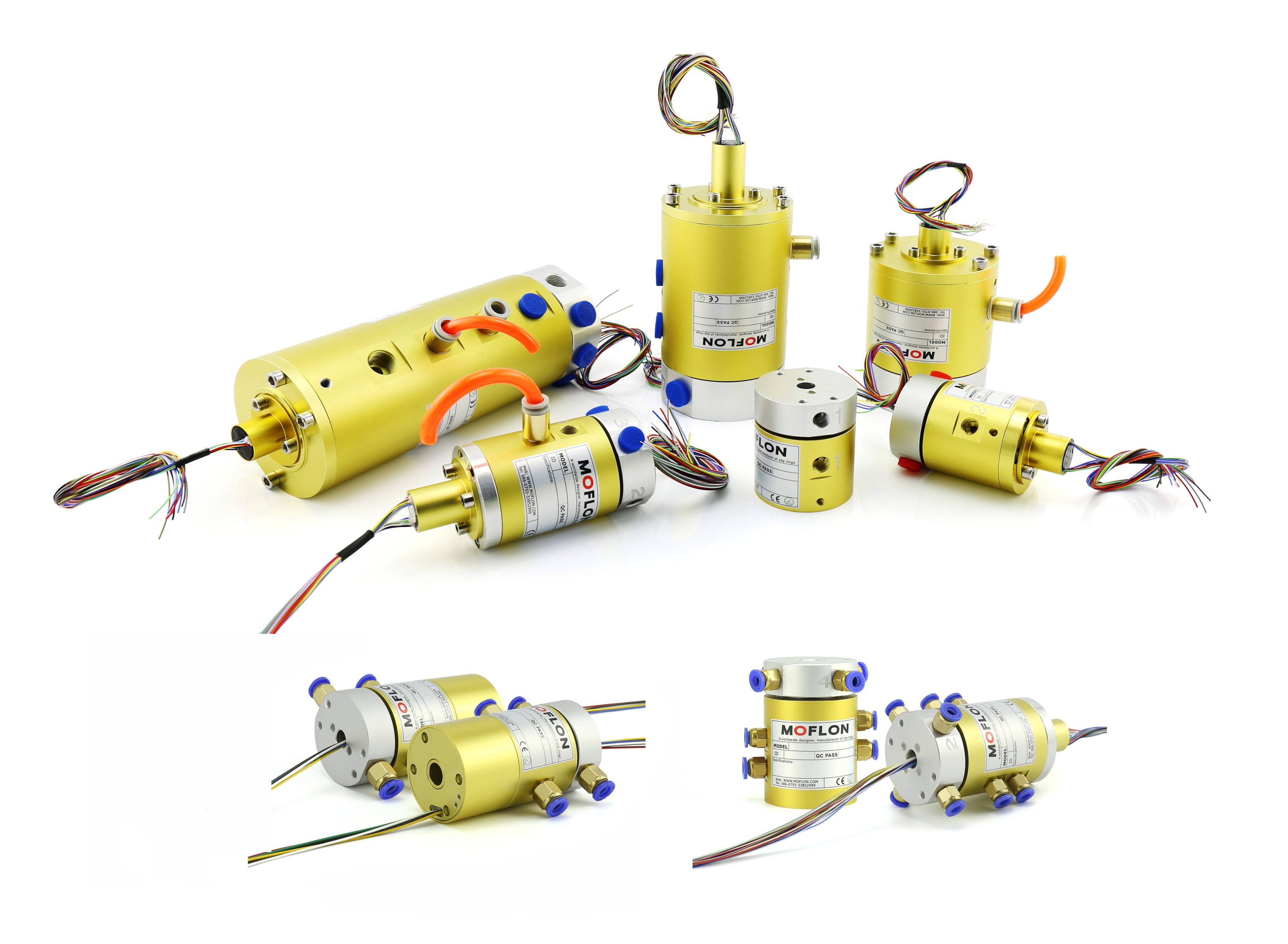
Rotary systems that rely on air or fluid transfer often fail quietly—pressure drops, leaks, or contamination build up long before anyone notices. Choosing the right air slip ring isn’t just about matching port sizes; it’s about selecting a component that can handle continuous rotation, mixed media, and harsh operating conditions without compromising signal integrity. In this guide, we compare practical options for dependable pneumatic and hybrid rotary connections, highlighting designs that minimize maintenance and downtime. One name that consistently appears in demanding industrial and marine applications is MOFLON, known for engineering air slip rings that combine compact form factors with reliable sealing performance. Instead of rehashing generic product listings, we’ll look at what actually separates a robust rotary union from a premature failure point—and which configurations make sense for your setup.
Why Most Air Slip Rings Fall Short of Their Rated Life
Most air slip rings carry a datasheet number that rarely survives contact with the real world. The rated life is calculated under clean, dry, low-speed conditions that factories almost never replicate. Airborne lubricant mist, compressor oil carryover, humidity swings, and the fine metallic dust from nearby rotating equipment all work their way past seals and into the brush track. Once that happens, wear accelerates in ways the original life estimate never accounted for.
The failure usually is not catastrophic at first. Contact resistance climbs, signal noise creeps into instrumentation channels, and pneumatic leakage rises slowly enough to be dismissed as normal. Operators compensate by increasing supply pressure or tightening fittings, but these fixes stress the internal seals further. By the time the slip ring reaches even half its claimed hours, it is often running hotter, passing less air, and delivering intermittent electrical connections.
A third factor is the way the rated life is presented. It typically assumes continuous rotation in one direction with a stable load, yet many machines stop, start, reverse, and dwell under partial pressure. That cycling is far harder on seals and brushes than steady motion. Without derating for actual duty cycle and contamination level, the published figure becomes more of a marketing benchmark than an operational promise.
Matching Channel Count to Real Rotary Workloads
Field experience with rotary machinery shows channel count should trace back to actual transducers, not a wish list. A gearbox with two bearing pedestals, one keyphasor, and three accelerometers needs six channels plus a spare; adding inputs for strain gauges or displacement probes without installed sensors just complicates setup. I would start by mapping every failure mode that has a measurable signature—unbalance, misalignment, bearing wear, torque ripple—and count only those channels.
Synchronous sampling changes the math. When you track shaft orbits or phase between inboard and outboard bearings, channel count is not just capacity; it is about simultaneous throughput at the highest shaft speed. Some systems list 16 channels but drop to multiplexed sampling above certain rates. For a turbine running at 12,000 rpm with eddy current probes and accelerometers, verify that all selected channels acquire in parallel; otherwise, channel count gives a false sense of coverage.
Spare channels should match plausible near-term changes, not hypothetical tests. If the only planned addition is a second keyphasor during the next overhaul, one spare is enough. Machines with frequent configuration changes—test rigs, balance stands, prototype compressors—benefit from a denser front end, while fixed process pumps rarely need that overhead. The goal is a measurement set that mirrors the rotor's actual behavior without paying for unused, unconnected inputs.
Seal Materials That Handle Dry Air and Temperature Swings
Dry air removes the thin lubricating film that many seal materials rely on, so friction and wear become immediate concerns. PTFE works well here because it slides against metal without sticking, but unfilled grades tend to creep under load. Adding glass or carbon filler keeps the seal dimensionally stable while preserving the low-friction surface that dry running demands.
Temperature swings introduce a separate problem: repeated expansion and contraction slowly eat away at seal lip force. FKM handles high dry heat but stiffens noticeably once temperatures dip, which can open a leak path before the system warms back up. Silicone stays flexible across a broader range, yet its tear strength and gas permeability make it a poor choice when the seal has to hold a pressure differential.
In many dry-air systems, HNBR or a filled PTFE energised cap offers a better balance. The groove should also allow for thermal movement instead of trapping the material rigidly. It helps to select compounds with low volatile content, since dry air accelerates the loss of plasticisers and leaves some elastomers undersized after a few hundred hours.
Pressure Drop Signs Your Rotary Connection Is Undersized
When a rotary connection starts choking flow, the first clue is rarely a gauge reading—it's the system working harder than it should. A drop in downstream pressure that widens under load often points to an undersized passage. The fluid has to speed up to squeeze through the smaller bore, and that velocity gain shows up as lost energy, not better performance.
Watch for pressure readings that sag only while the circuit is moving or when multiple actuators demand flow at once. If the inlet side holds steady but the outlet side falls further than expected, the rotary union is acting like a restrictor. In hot oil or steam lines, this restriction also tends to run hotter at the joint because the pressure energy converts into heat rather than useful work.
Over time the symptoms compound: seals take the punishment from high internal velocity and uneven pressure distribution, which leads to weepage or premature scoring. Rather than compensating with higher pump pressure, it's worth checking the connection's flow capacity against the actual demand. In many cases, stepping up one size restores pressure stability and quiets the system down.
What Maintenance Teams Miss When Air Paths Get Noisy
When an air handler starts whining or rattling, the instinct is usually to grab a grease gun or swap out a bearing. That is the obvious path, but noise in an air path often carries a message from somewhere less convenient. A sudden change in tone on the return side can point to a loose duct liner that has peeled back and started fluttering, or a fire damper that no longer stays fully open when airflow increases. These get missed because they do not always show up during a quick visual inspection, especially when ductwork runs through a ceiling or shaft with limited access.
Another blind spot is the interaction between components. A noisy fan might be blamed on the motor, but the real trigger can be a V-belt that has settled into the sheave grooves, producing a rhythmic slap that travels along the duct and sounds like a mechanical fault at the unit. Likewise, dirty turning vanes or a partially closed balancing damper can push the system into a less stable part of its performance curve, causing turbulence that reads as a bearing issue at first. Teams often replace the parts that spin, only to hear the noise return weeks later because the cause sits upstream in the air path.
There is also the habit of tolerating noise until it becomes part of the background. Maintenance crews sometimes inherit a system that has been loud for years, so they stop treating the sound as a symptom. Yet shifts in frequency often precede failures that are cheaper to fix early. A high-pitched whistle at a coil cabinet can mean air is bypassing a filter that no longer seats correctly, and that bypass erodes coil fins while pulling dirt deeper into the system. Noticing those changes, instead of chasing only the loudest component, is where the real diagnostic value lives.
Building a Shortlist Around Duty Cycle Instead of Diameter
Diameter is the easiest first filter because it is visible and simple to measure, but it rarely predicts how long a component will survive in a real operating rhythm. A shortlist built on diameter tends to collect parts that fit the mounting space while quietly ignoring whether they can handle frequent starts, long continuous runs, or uneven load spikes. That oversight usually shows up later as excess heat, worn contacts, or unplanned downtime.
Flipping the order changes the conversation. Start with the actual duty cycle: how many minutes per hour the equipment runs, how hard it works during those minutes, and how much rest it gets between cycles. Compare that profile against manufacturer ratings rather than starting with a dimension range. Diameter still matters, but it becomes a final installation check instead of the gate that shapes the whole list.
The practical payoff is a shorter list of genuinely compatible options. A team that filters by duty cycle may end up with a slightly larger housing or a different frame size, but the selected unit tends to run cooler and last longer under the same daily load. In many cases, the best shortlist is not built around the narrowest space available, but around the rhythm the equipment actually has to endure.
FAQ
Start with the number of independent air passages, the maximum pressure and flow each channel must carry, and the expected rotary speed. Seal material, bore size, torque resistance, and how easily the unit can be serviced matter just as much as the headline specs.
A standalone rotary union typically handles only fluid or air, while a hybrid unit combines pneumatic channels with electrical power or signal paths in one rotating assembly. That saves space and simplifies routing when a machine needs air and data moving through the same joint.
Stainless steel and anodized aluminum bodies resist corrosion well, while PTFE, Viton, and high-grade nitrile seals handle different temperature and chemical exposures. The right pairing depends on your air quality, humidity, pressure, and whether the environment is washdown or high-heat.
Yes, multi-passage designs are common. The key is making sure each channel is isolated well enough to prevent cross-leakage, especially when lines run at very different pressures or carry different gases.
Dirty or wet air, pressure spikes, misalignment during installation, and running at higher speeds than the seals are rated for are frequent culprits. Even a small amount of particulate wear can degrade sealing surfaces over time.
They can be, particularly when the bore has to clear shafts, cables, or tubing in a tight envelope. A well-matched bore reduces sharp bends and strain on internal plumbing, which often lowers the chance of leaks and premature wear.
Seals can stiffen in cold conditions or soften and swell when hot, changing friction and leak behavior. Choosing a unit with seals and lubricants rated for the full operating temperature range prevents most seasonal or process-related surprises.
Monitor pressure drop for early signs of internal leakage, keep upstream air filtration clean, and check fittings for movement or loosening. Periodic seal inspection and replacement before visible wear develops usually costs far less than fixing a failed joint later.
Conclusion
Air slip rings rarely fall short because the catalog number was wrong on paper. More often, the rated life assumes a clean, steady air supply and a moderate duty cycle, while the actual installation sees dry air, temperature swings, and long idle periods that harden seals and invite microleaks. When evaluating options, start by matching the number of channels to the real rotary workload rather than choosing the largest housing available. A four-passage unit may look versatile, but unused ports simply add potential leak points and make pressure drop harder to diagnose. Look for seal materials that stay pliable under cold starts and do not glaze when compressor discharge air runs hot. If the pressure gauge at the tool drops noticeably during rotation, the rotary connection is probably undersized or the internal passages are too restrictive for peak flow demand.
Noise is another signal maintenance teams often dismiss as normal wear. Hissing or whistling along the air path usually points to a seal lip fluttering, a partially blocked passage, or a bearing that has developed enough play to alter running clearance. Instead of waiting for a rebuild, shortlist candidates by duty cycle and flow continuity rather than by outside diameter alone. A compact unit built for continuous indexing may outlast a larger, heavier model rated only for intermittent motion. The most reliable choice is not the one with the most impressive static specifications, but the one whose seal compound, channel arrangement, and pressure behavior align with how the rotary axis actually runs day after day.
Contact Us
Contact Person: Xiangpin Li
Email: [email protected]
Tel/WhatsApp: 86 186 1706 8578
Website: https://www.moflon.com